Microprocessor Based Sequential Timers
We are Manufacturer, Supplier, Exporter of Microprocessor Based Sequential Timers, from Pune, Maharashtra, India.
The sequential operation of the micro controller controls the solenoid valve `ON’ Time and `OFF’ Time, which in turn allows the compressed air to be injected into the filter bags for cleaning purpose. There is a time base (clock), which generates the clock pulses for the operation of the timer. These clock pulses are shaped and processed through CMOS circuitry to get required pulse for triac firing circuit. These triacs in turn control the solenoid valves. The clock pulses are adjustable to get the required `ON’ and `0FF’ duration.
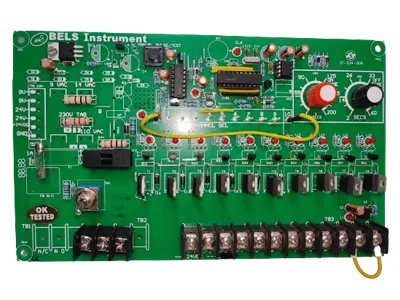
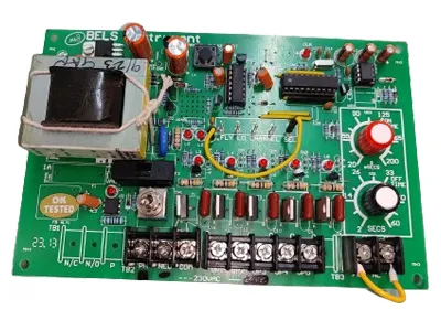
Refer the PCB wiring Diagram No. 050774, Dt.29 -01 -2014 at the end of this Manual (The ident is printed on the PCB as well). The legends used in this are Detailed below (From Left To Right):
Pr. Sw. (P1)
D.P. Switch Contact (Use N/C contact)
Pr. Sw. (P2)
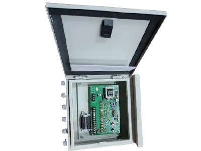
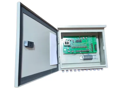
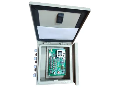
Once these are understood thoroughly, open the front cover of the equipment by loosening two wing Nuts provided. By using Knockout gland plate for input & output connections for suitable wire. If the Pressure Switch Connections are not required or not utilized, do not make any change in the connections with the Timer provided. But if it is not so then connect it as shown in the Diagram provided. (IF PRESSURE SWITCH INTERLOCK IS NOT REQUIRED, THE TERMINALS P1, P2 MUST BE SHORTED.)
PHASE (LIVE) must be connected to Electrical Phase of the Power Supply. This should be observed strictly otherwise equipment will give shocks if any portion of the circuitry is touched by bare hands). `N’ must be connected to Electrical `N' or Cold connection.
`ON' Time Setting KNOB (Red / Grey Colour Knob) Duration Settable: 20 mSec. To 200 mSec.
`OFF' Time Setting KNOB (Blue / Black Colour Knob) Duration Setting: 2 Secs. To 60 Secs.
This is done by setting the flying lead of the programming system to the required No. of channel required at the output i.e. for 3 way output reset lead (Yellow / Red / Blue) to 3rd Pin and for 5 Way to 5th Pin and so on.
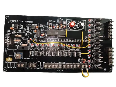
Manual pulsing of outputs can be done by MANUAL P.B switch. The output of each solenoid valve can be checked sequentially by using PUSH BUTTON (P.B.) provided switch on PCB. (top center of PCB). At time of manual pulsing, you should keep "OFF TIME" pot on maximum position. After finishing manual pulsing Timer automatically goes to Auto Mode (pl. check OFF TIME which you required)
P1, P2 Terminals (TB 4) on sequential controller stops functioning when contact at P1, P2 Open. Sequence continues from point where it had stopped when contact reopens.
Function Indicator LEDs are very useful version of this sequence controller. They indicate both status and functioning of the sequence controlling triacs as well as solenoid valves. Following Table describes the complete operation if these LEDs and how useful it is to diagnosis the triacs and solenoids :